Traildonkey 4.0 – Owner’s Manual
This owner’s manual seeks to cover all of the uniquely developed features debuting exclusively on the new Traildonkey 4 frameset.
Lockjaw Slider System…
The Lockjaw slider system was specially developed to allow for a sliding dropout system in a carbon adventure frame. Its design minimizes the torque needed to keep a slider system in place by utilizing metal teeth embedded into the carbon frame; this means the carbon frame is not damaged by the torque required for a typical slider system. A sliding dropout system allows a range of setups for your specific wheel and tires or preferred ride feel, as well as singlespeed chain tension adjustment. A longer wheelbase is more stable, while a shorter base is more nimble. A larger tire will need to be slid further back, while a road tire can be tucked in nice and tight.
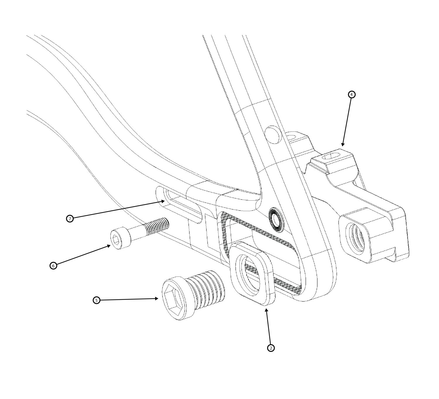
Dropout / Lockjaw Exploded View 1

Our system utilizes:
- Metal Lockjaw teeth embedded into the frame
- Two outboard Lockjaw compression plates (2)
- Two slider compression bolts, one per side, that sandwich the compression plates to the frame.
- The driveside compression bolt bore is threaded inside for the thru-axle threads (1), the non-driveside compression bolt bore is smooth to allow the axle to pass through (5).
- We provide a 6mm to12mm hex adapter tool with each frame to assist with this installation. 12mm hex tools are uncommon, so do keep track of the tool that we supply so that you have one when needed. Alternatively, 12mm hex sockets can be found at some automotive stores or online.
- The sliding dropouts, non-driveside (4) and driveside (3)
- A brake torque bolt and accompanying oval washer (6, 7)
- The rear thru-axle and accompanying axle tool
The easiest and most effective way to set up your sawtooth slider system is in this order:
- Place the non-driveside slider (4) into the frame slot from the inside.
- Place a Lockjaw compression plate (2) onto the fixing bolt (5) with the smooth bore, loosely thread the bolt into the non-driveside slider.
- Do the same with the derailleur hanger (3) on the drive side, this time use the fixing bolt that has a threaded bore (1).
- The sliders should be able to move freely at this time.
- With your preferred rear wheel and tire, place the hub into the dropouts and slide in the rear thru axle to loosely mockup the approximate location you want the wheel to sit.
- Holding the non-driveside slider in place, remove the axle and hub and tighten the non-driveside fixing bolt (5) to 15Nm in this mockup location.
- Ensure the compression plate teeth are engaging into the frame teeth when tightening a slider compression bolt. Do not tighten the compression plate sideways on the teeth, or onto the carbon frame.
- Insert and tighten the brake torque bolt with its accompanying oval washer (6, 7) to 8Nm with blue locktite.
- Place the wheel back into the sliders, slide in the thru-axle and thread just a few turns into the driveside fixing bolt. This will position the driveside slider properly. Ensure that the wheel and tire are sitting centered between the chainstays to ensure the slider is in a good position.
- When satisfied with the alignment, tighten the driveside slider fixing bolt to 15Nm. Fully tighten the rear axle to secure the wheel.
- At this point, the rear brake can be affixed/adjusted, the chain can be sized and cut, and the derailleur(s) can be affixed/adjusted.
- When using a singlespeed setup, it is at this point you can cut the chain to the approximate size. If you have tucked the tire toward the frame, cut the chain on the long side and reposition the sliders equally backward on the Lockjaw to achieve proper chain tension. If you have adequate forward tire clearance, you are free to cut the chain either too short or too long and adjust tension using the teeth in equal increments on each side.
Dropout Exploded View 2
Seatpost Collar and Shim…
When we designed the latest Traildonkey, we wanted to allow the widest possible range of components to be used on the frame. When it comes to seatposts, this is highly relevant. The compliance of a 27.2mm carbon seatpost while gravel riding or racing is unmatched, but whilst shredding the gnar, the best range of travel and product options for dropper seatposts clearly favors a diameter of 31.6mm. In response, we decided to make the frame 31.6mm native, but also provide a special seatpost shim to all customers so they can step down the frame to 27.2mm (8, 9).
- The frameset is shipped with the shim installed, so if you are using a 27.2mm seatpost, no additional setup is required. Just apply assembly paste to your post, insert, and torque to at least 5Nm.
- If you desire to install a 31.6mm post, simply loosen the seat collar, pull out the shim, install the provided 31.6 collar spacer into the collar, place the collar back on, and install your post. Torque to at least 5Nm.
- It is important to remember that an additional part like a shim introduces additional variability into a system that already has its own set of tolerances. Some posts will require higher torque, some will require less. Depending on the post, it is not uncommon for the bolt to require 8Nm of torque in order to clamp the post with the required force to hold it securely in place.
- If you are nervous to overtighten your carbon seatpost, test ride on the post at increasing increments of torque by 1Nm, starting at 5Nm, until the post does not slip. If the post was just slipping at a previous torque value, you are not going to damage the post with the next increment of 1Nm.
If the shim has been removed, the re-installation of the 27.2mm shim and seatpost is simple:
- Remove the TD4 collar. You may need to loosen the bolt a little…
- Slide the shim (8) into the frame with carbon grip paste on the inside and outside. We recommend using assembly paste on all Rodeo Labs bikes to ensure that your seatpost stays put in all conditions.
- Align the shim so that the protruding c-clip (9) tip is pointing forward toward the handlebars. Slide it all the way down until the c-clip touches the seattube.
- Slide the TD4 collar on such that the c-clip tip sits between the open slot in the collar. Shimmy the collar until it bottoms out onto the frame and shim.
- Slide in your 27.2mm post and torque to at least 5Nm.
Seatpost Shim Exploded View
Downtube Storage Door…
It’s a hole! In the frame! Put stuff in it! But not too much stuff!
The door is designed to open simply by depressing the button near the top, then sliding sideways or forward, not upward or backward. It is designed to not break if pulled directly upward, but it will feel more fussy when done this way. To reinstall, hook the bottom side first, then when the button is pushed back onto the ball it should pop back up nice and flush. We tune each door button before it leaves, but in the event you experience a maladjusted door we are here to help.
Inside the storage compartment, you’ll see some nifty cable tie down features affixed to the bottom of the downtube with bolts and a nut to prevent rattling. When tightening, use blue Loctite and don’t exceed 3nm. They don’t need a lot of torque to serve their function and going any tighter will likely damage the plastic tie down.
Pro Tip: Use an adjustable wrench to align the bottom hook when tightening the compression nut. As you get to higher torque, the hook can rotate. Using an adjustable wrench ensures perfect hook alignment with minimal effort.

If your button feels sticky or doesn’t pop back up when pushed onto the ball:
- Don’t be afraid to apply a good amount of pressure to get the button to fully engage! It also helps to press down firmly directly above or below the button.
- First try cleaning all the contact points of the door and lubricating the underside internals of the button with a lubricant like TriFlow. Mmm bananas…
- Just like any other part of your bike, the door hardware may require occasional maintenance if it has been exposed to harsh elements. Grime and grit can affect the functionality of the button so if it gets dirty a little compressed air and/or WD40 will bring it back to life. For those that just want to seal the system up or add a splash of color to your Traildonkey, we now offer the Traildonkey 4 Button Seal kit.
- If this did not fix it, you could have too much stuff inside blocking the button or door from compressing fully onto the ball.
- If that also did not fix it, a button shim will need to be removed from between the button and the topside of the door. Remove the button nut on the underside of the door, shimmy the button out, and remove 1 shim. Reattach the button and test that the button now engages. Be sure this did not introduce any play into the door.
If you are experiencing a loose or rattly door:
- First ensure the button is depressing fully onto the ball and the button pops up when pushed onto the frame. Check if the button backing nut has loosened. Lubricate the button internals. Be sure it is not the bottle cage bolts or threadserts that are causing a noise. Check that the rubber elastomers near the ball are still present and in good condition. Check that the lower door hook is not damaged or loose.
- If that did not fix it, a button shim will need to be added between the button and the topside of the door. Remove the button nut on the underside of the door, shimmy the button out, and add 1 shim. Reattach the button and test that the door now does not move side to side or make noise. Be sure this did not cause the button to not fully engage onto the ball.
- If you still hear a rattle, ensure that it is not caused by brake or cable housing, or items that are stored inside of the frame. Any hard object that has free movement inside of the frame could cause rattle, so be sure to secure items inside the frames with the supplied velcro straps, or store your items in your frame inside of a padded wrap or pouch.
- If you ride in filthy or wet conditions it is good to maintain the button assembly by hitting it with compressed air and eject any dirt that works its way into the system. Also lubricate the system from time to time with Tri-Flow or similar in order to keep the internal parts in best condition. If you ever find that the button is functionally compromised, rest assured that the button is replaceable and we will offer replacements for sale. In our thousands of miles of test riding in all conditions we have not yet seen button reliability issues or performance degradation.
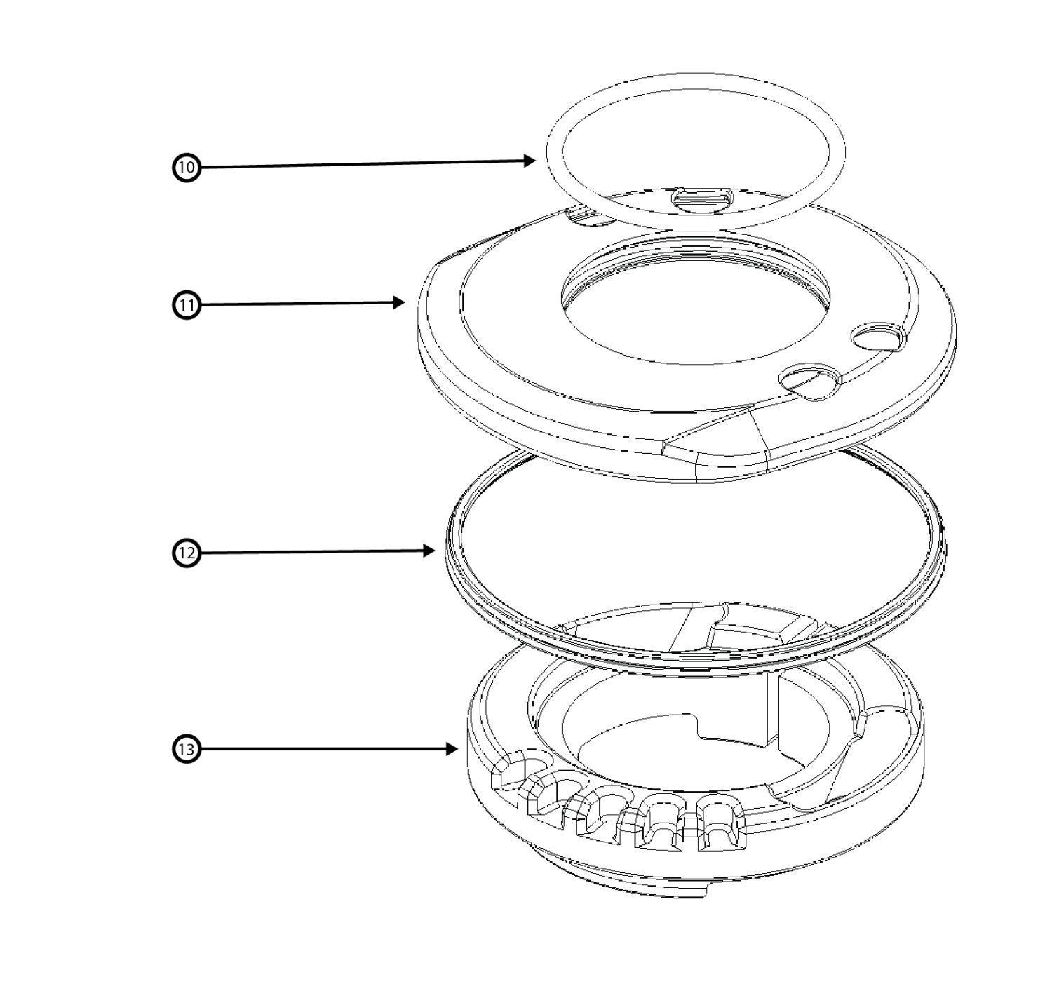
Quite Nice Headset Exploded View
Quite Nice and Integrated Headset…
When we saw that integrated routing was a thing, we just haaaaaaad to have it as an option. However, there were many drawbacks to the current integrated routing systems. They required a full set of compatible headset, stem, and bar, and were difficult to install. Integrated routing also tended to be a less sealed system than standard headsets, leaving the bearings vulnerable to water and dirt. We created a semi-integrated headset system that comes with all framesets that allows for a simpler install, more accessible maintenance, and just about any stem and bar combo you want. Our supplied headsets also feature upper cover seals for longer bearing life and lower maintenance needs.
Here are some pointers on using this headset system:
- Ensure the steerer o-ring (10) is on the inner lip of the upper cover, and the large outer seal (12) is seated nicely around the outer lip. This protects the bearings from water and debris.
- You will notice the upper race (13) and cover (11) feature holes and notches. You can use the notches to decide how many routing holes you need for your setup. It can be set to zero holes if you are routing using the frame routing ports and incrementally set up to 4 routing holes.
- When routing, be sure the housing takes nice natural bends into the headset to ensure shifting quality and undamaged brake hose, and that they are not pulled extremely tight. The right setup will have the housing running cleanly and smoothly in line to the left and right of the stem and steerer.
- If your aim is the most friction free mechanical shifting performance, we recommend using the frame housing routing ports instead. Although we have ridden many derailleurs through this headset successfully, semi-integrated routing simply has tighter bends and more friction housing path can sometimes affect the shifting performance.
- We do not recommend using the headset cover to route a dropper post. Although possible, and we have tested it, it leaves inadequate room for the barrel adjuster (unless placed in the downtube), is more difficult to cut to the proper length, and presents a real maintenance and removal headache in the future that requires unclamping the dropper cable from the remote. We recommend simply using the frame port on the downtube for droppers for the best experience, or a wireless AXS dropper can be used.
- It is possible with a wide variety of stems to fully slam your steerer stack for maximum speed mode, an intentional design feature. However, we haven’t tested every stem in the world, so there may exist some bulky blocky stems out there that will partially block the headset holes if slammed all the way down.
- If the metal of the headset cover (not the seal) rubs the frame due to paint/clear coat variance, use the included shim underneath the upper to raise it away from the frame.
- This headset cannot be paired with other integrated routing systems, such as Ritchey or FSA. If you are using fully integrated housing on your build you must pick one brand of housing integration system to use on your bike, and you must also purchase and use the headset designed for use with that system separately. For example the FSA integrated bar / stem / routing system must use the FSA integrated system headset.
Spork 3.2…
TD4 is paired with its own more holey Spork variant that allows integrated (internal) front brake routing that runs through a hole at the base of the steer tube then into the fork leg through the fork crown. It is otherwise identical to the Spork 3.0 / 3.1. We retained the exterior leg routing hole if you want to keep things simple and easy when routing the brake, but also included the steerer routing hole if your aim is clean looks.
This added routing hole produced another hidden benefit. It is possible to squeeze a rear dynamo light wire through it alongside the brake hose to achieve a fully-integrated, human-powered lighting system. It is a tight fit, but we’ve done it successfully! Pair it with our custom rear dropout light mount and you’re looking sharp as a marble.
On the smaller frame sizes, 54cm and 52cm, the offset of the Spork has been changed to 50mm, as opposed to the standard 45mm. This helps retain more similarities in ride feel on these bike sizes.
We currently do not offer the integrated spork option on Flaanimals or for standalone retail sale, nor do we offer 50mm offset forks outside of the 54cm and 52cm TD4 framesets. BUT, be patient and we may be able to offer these options to all riders in the near future.